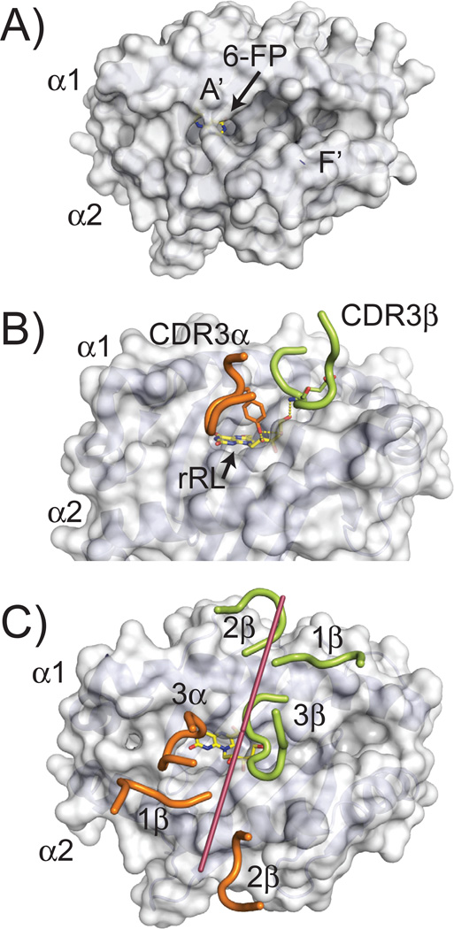
Fig. 7. MR1 ligand presentation and recognition by MAIT TCRs.
(A) Surface representation of human MR1 (PDB ID: 4GUP) showing the cavity structure of its antigen binding groove. Two main cavities are apparent, called A′ and F′. The 6-FP ligand identified in the crystal structure, is barely visible, colored in yellow (carbon atoms) and blue (nitrogen atoms). (B) Positioning of the CDR3α and CDR3β loops of a MAIT TCR in the complex structure with MR1 presenting the rRL ligand (PDB ID: 4LCC). The residues in these loops that contact the rRL ligand are shown, Y95 for the CDR3α loop and E99 for CDR3β. Hydrogen bonds established between these residues and the ribityl chain of the rRL ligand are shown as dashed yellow lines. (C) Orientation of the MAIT TCR CDR loops while docked onto the MR1 structure. Similar representation as to Figure 2; line was drawn (shown in raspberry) from the two external conserved cysteines in the Variable Ig domain of the MAIT TCR (C22 of α chain and C23 of β chain) to demonstrate orientation of the TCR on the MR1 surface. CDRα loops are colored in pink; CDRβ loops in green. The rRL ligand is shown as sticks in yellow (carbon atoms) and blue (nitrogen atoms).

