Figure 2.
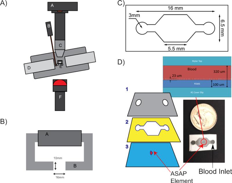
A) Diagram of the experimental setup, where: A is the 120 fps Pulnix camera; B is a gauss probe; C is a 10x Plan Nikon lens; D is the soft iron electromagnet; E is the heated holder for the ASAP element; and F is the diffuse near-infrared LED. B) Top down view of the electromagnet. A is the magnetic coil, and B is a silicon steel tape wound core. The gap is 16 mm wide and the faces are 10 by 10 mm. C) Diagram of the micro-fluidic chamber used for the blood experiments. The entire channel is 200 μm tall. D) A schematic showing the layers used in constructing the micro-fluidic chamber, where: 1 is a Mylar top with air vents cut out; 2 is an adhesive spacer that defines the chamber dimensions; 3 is a #1 18x18mm coverslip with the post array mounted in the center. These layers are adhered to produce the final device as shown in the bottom-right. The blood droplet is put on one of the two ports and wicks into the device through capillary action. A side view of the post array in a channel filled with blood is shown above channel.

