Fig. 3.
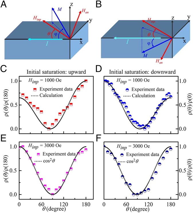
Estimation of the tilt direction. The schematic configuration of the coordinate system used in the analysis of the AMR data. A and B show the configurations for the initial polarization of up and down, respectively. The sense current for AHE measurement flows along direction pointing to the long axis of the nanomagnet. θ is the angle between the directions of the measurement current and the external in-plane field Hinp. θ = 0 corresponds to the orientation where the applied field is aligned to the direction of current flow. θ was taken as positive for an anticlockwise rotation of the field from current. φ is the angle between M and I. Calculated and measured values of AMR resistivity are shown when |Hinp| = 1,000 Oe and the magnet was initially polarized (C) upward and (D) downward. Calculated and measured values of AMR resistivity are shown when |Hinp| = 3,000 Oe, and the magnet was initially polarized (E) upward and (F) downward.

