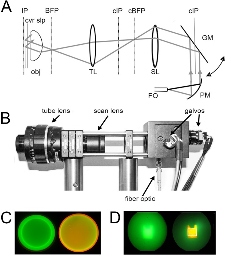
Fig 1. Optical scheme of the spinning spot TIRF illuminator.

(A) Optical schematic. Laser light from a single-mode fiber optic (FO) is collimated by a parabolic mirror beam expander (PM) and directed onto a pair of orthogonal galvanometer-driven mirrors (GM: only a single mirror is shown for clarity). Reflected light is relayed through a scan lens (SL: formed by a 10x eyepiece) and a tube lens (TL: formed by a 50 mm f 1.8 camera lens) which focus the laser light to a diffraction-limited spot at the back focal plane (BFP) of the microscope objective (obj). A dichroic mirror placed between the tube lens and objective (not shown) reflects laser light to the objective, while allowing emitted fluorescence to pass through to the imaging camera. IP = image plane; cIP = conjugate image planes; cBFP = conjugate back focal plane. (B) Photograph of the spinning spot TIRF illuminator, constructed from Thor Labs optical cage components. (C, D) Photographs taken through the microscope ocular, illustrating the alignment procedure using a rhodamine film/fluorescein solution test specimen. (C) Images taken with a Bertrand lens present so as to view the back focal plane of the objective lens. The left panel shows the narrow green circle traced by the spinning lase spot when the radius is set below the critical angle for total internal reflection. The right panel was captured after increasing the scan radius to achieve TIRF excitation. The appearance of the orange ring arises from selective fluorescence excitation of the film of rhodamine within the evanescent field. (D) Corresponding appearance of the fluorescein solution/rhodamine film test specimen viewed conventionally (i.e. without the Bertrand lens) with the radius of the scan circle below (left) and above (right) that required for TIRF excitation. The white box in the right panel outlines the approximate imaging field of the EMCCD camera.
