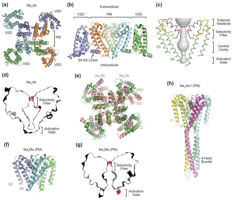
Figure 2. Overall Structures of Prokaryotic NaV Channels.
(a) Structure of the NaVAb bacterial NaV channel determined at 2.7Å resolution and viewed from the extracellular side [9]. The four subunits of the homotetrameric channel are shown in different colors. The central pore is surrounded by four VSMs. (b) Side view of NaVAb with the same coloring scheme as shown in (a). S5 and S6 helices of one subunit (slate) and the VSM of another subunit (cyan) are omitted for clarity. (c) Architecture of the NaVAb pore with pore volume shown in grey and the high-strength-field (HSF) site residue Glu177 shown in sticks. P and P2 indicate the P and P2 helices. (d) Cross-section of the NaVAb pore showing the closed activation gate. The selectivity filter is shown with electrostatic surface potential colored from −50 to 50 kT (red to blue). (e) Superposition of NaVRh and NaVAb with their PMs superimposed [9, 11]. The VSM of the two channels packs against the PM at different angles. (f) Structure of the NaVMs pore module [13]. (g) Cross-section of the NaVMs pore showing the open conformation of its activation gate [18]. The selectivity filter is shown with electrostatic surface potential colored from −50 to 50 kT (red to blue). (h) Structure of the NaVAe1 pore with well-resolved C-terminal domain forming a four-helix bundle [15].

