Figure S7.
Disorganization of Blood Vessels Leads to Disrupted Schwann Cell Migration and Axonal Regrowth, Related to Figure 7
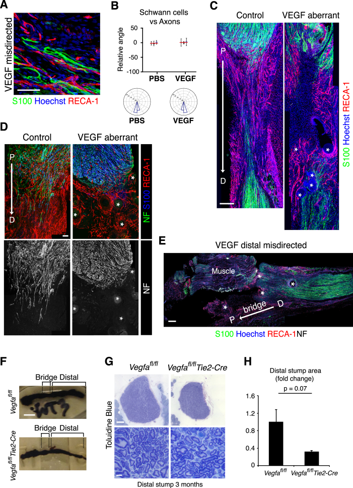
(A) A higher magnification of Figure 7B to show the Schwann cell cords (S100+, green), aligned to the blood vessels (RECA-1+, red). Scale bar = 50 μm.
(B) Quantification of Figure 7B to show the alignment between Schwann cells and regrowing axons. Graph shows the mean relative angle ± SD for each animal with the mean between animals shown by the red lines. Rose plots show the distribution of cells for all animals (n = 3 animals for each condition).
(C) Images of bridge regions of a control (PBS) and VEGF-treated rat sciatic nerve, Day 6 after injury, immunostained to detect Schwann cells (S100+, green) and endothelial cells (RECA-1+, red). Nuclei were counterstained with Hoechst (blue). Scale bar = 300 μm. The beads are indicated by white asterisks in the VEGF-treated animals. Note the center of the bridge is poorly vascularised in the VEGF-treated mice and the Schwann cell cords fail to enter the bridge.
(D) A further example of aberrant regeneration in a VEGF-treated sciatic nerve. Upper panels show images of a bridge region of control (PBS) and VEGF-treated rat sciatic nerves, Day 6 after injury, immunostained to detect Schwann cells (S100+, blue), endothelial cells (RECA-1+, red) and axons (NF+, green). Scale bar = 100 μm. Lower panels show the same images as in the upper panels, filtered to show only the axons (NF+, white). Note the axons in the VEGF-treated nerves are misdirected, toward the beads, into the adjoining muscle.
(E) Image of a disconnected nerve following treatment with VEGF-treated beads in which the beads redirect Schwann cell cords from the distal stump. Note the blood vessels (RECA-1+, red) and Schwann cells (S100+, green) are directed away from the bridge into the surrounding muscle. Scale bar = 200 μm. For reconstruction of longitudinal sections shown in (C), (D) and (E), multiple images from the same sample were acquired using the same microscope settings.
(F) Images of nerves stained with osmium tetroxide taken from Vegfafl/fl (control) and Vegfafl/flTie2-Cre mice, 6 months following transection. Note the visibly smaller distal stump in the mutant mice. Scale bar = 2mm.
(G) Cross sections of a nerve from Vegfafl/fl (control) and Vegfafl/flTie2-Cre mice 6 months following transection and stained with toluidine blue, at low magnification to show the entire nerve (top panels) and at higher magnification to show the indistinguishable structures of the control and mutant nerves (lower panels). Scale bar = 100 μm (top) and 5 μm (bottom).
(H) Graph to show the difference in area between the Vegfafl/fl (control) and Vegfafl/flTie2-Cre nerves as in (G), n = 3; graph shows the mean ± SEM.

