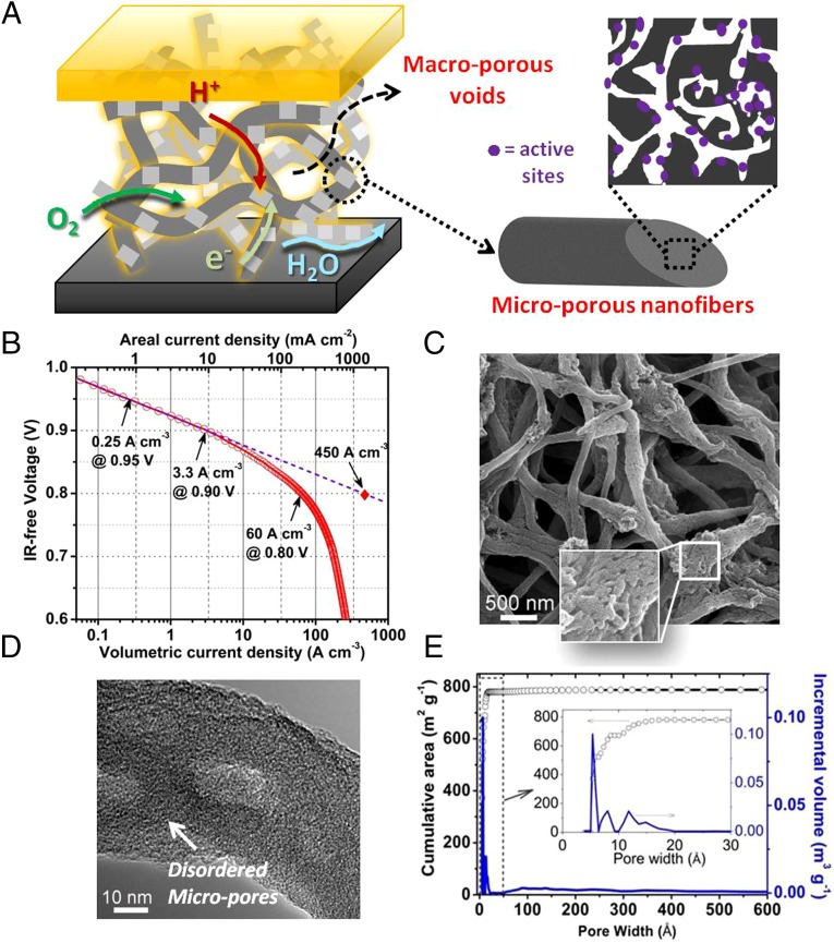
Fig. 1.
The nature of Fe/N/CF catalyst, its volumetric activity in a PEM fuel cell, and its distinct micropore–macropore architecture. (A) A schematic drawing of macropore–micropore morphology and charge/mass transfers in the nanofibrous network catalyst, Fe/N/FC, at the fuel cell cathode. (B) Tafel plot for the kinetic activity of Fe/N/CF obtained from a single fuel cell test. The volumetric current densities (bottom x axis) at 0.95, 0.9, and 0.8 ViR-free were derived by dividing the measured areal current densities (top x axis) over the cathode layer thickness, which was 30 µm in this case. The value of the extrapolated volumetric current density at 0.8 ViR-free was also provided. For the fuel cell test, the cathode catalyst loading was 2.0 mg⋅cm−2 with ionomer-to-catalyst weight ratio (I/C) = 1/1. The membrane was Nafion N117. Cell and fuel gas temperatures were maintained at 80 °C. The O2 and H2 absolute pressures were at 1 bar with total pressure of 1.5 bars at each electrode, including ∼0.5 bar water vapor pressure under 100% relative humidity (RH) at 80 °C. (C) SEM image of the Fe/N/CF nanonetwork catalyst. (D) High-resolution TEM image of a thin catalyst fiber. (E) BET isotherm analyses on cumulative surface area and incremental pore volume as the functions of pore size in Fe/N/CF.

