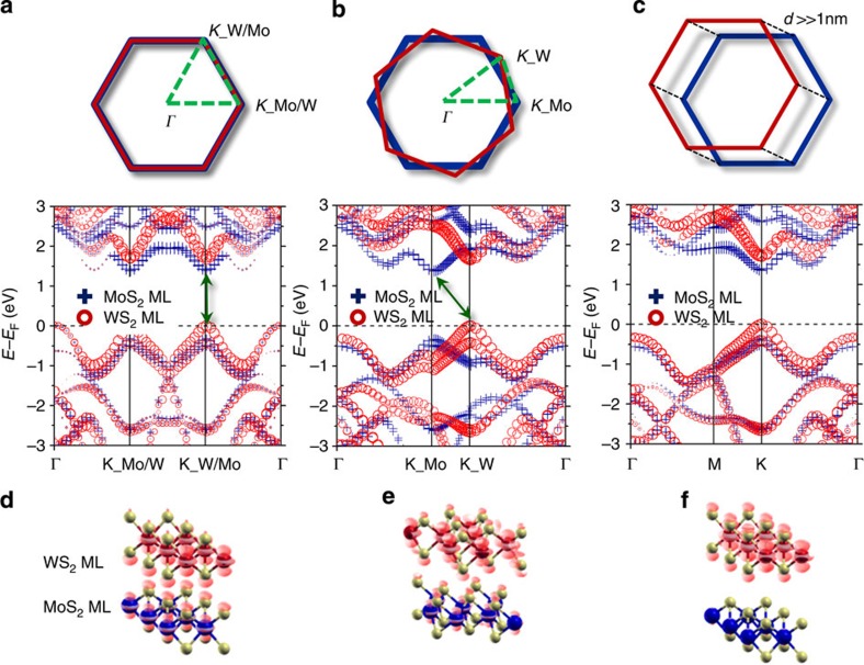
Figure 4. Band structures of coherent and random stacking MoS2/WS2 bilayers and partial charge density plot of MoS2/WS2 bilayers.
Band structures of (a) coherent and (b) random stacks. Here we consider random stacking with a rotation by 21.79° between two MLs. The upper figures represent the overlap view of the primitive cell Brillouin zones for each stacking type. Dashed lines on the Brillouin zone indicate the k path, which the band structures are calculated along. The coherent and random stacking bilayers show the direct- and indirect-bandgap features, respectively. Each contribution from MoS2 ML and WS2 ML is denoted by the size of the blue crosses and red circles, respectively. (c) The band structure of coherent stacking with large distance (d≫1 nm) between two layers. (d–f) The partial charge density plot of the structure used in a–c at the Γ point in the VB.

