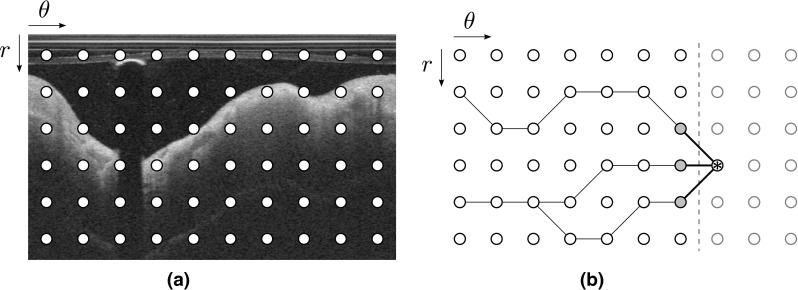
Fig. 2.

Schematic representation of the front propagation scheme, corresponding to the panel (f) in Fig. 1. a Original polar image, with the pixels represented by the nodes (in this example, the layout is coarse for improved visibility). b Left-to-right front propagation, with the current location of the front indicated by the vertical dashed line. The current node is indicated by an asterisk, and the connected gray nodes correspond to the set of potential neighbors. In this example, the number 2N + 1 of horizontally reachable neighbors is equal to 3. The black lines connecting the nodes represent the successive backtracking steps from a given node to the left border of the image. Please note that in the case of segmenting the luminal interface, the nodes of the upper row correspond to the top of the polar image (as shown in this example), whereas in the case of the segmenting the abluminal interface, the nodes of the upper row correspond to the luminal interface
