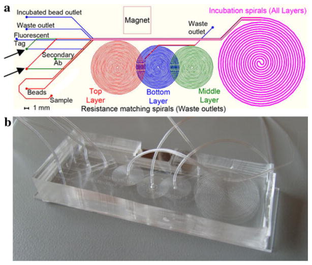
Fig. 4.
a Device layout, each of the smaller spirals performs flow resistance balancing on one of the three layers, and the large incubation spiral is identical on all layers. The top layer is shown in red, the middle layer in green, and the bottom layer in blue. Overlayed layers are shown in fuchsia. Layer transfers are depicted with arrows. b Photograph of complete three layer PDMS microdevice (color figure online)

