
Fig. 1.
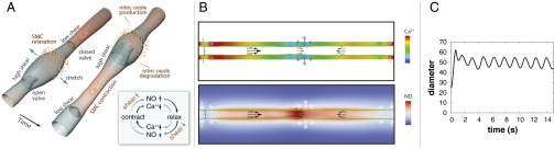
Dynamics of lymphatic pumping. (A) Conceptual scheme, showing two different snapshots of cyclic lymphatic pumping. Flow direction is from Bottom Left to Top Right. Nitric oxide relaxes the vessel wall, increasing vessel diameter and pulling fluid from upstream. As the lymphangion fills, the upstream valve is open, and the downstream valve is closed. When the lymphangion is filled, flow and shear stress decrease, and NO is degraded; a subsequent contraction can be initiated through Ca2+ influx via stretch-, voltage-, or ion-activated channels. The contraction closes the upstream valve and opens the downstream valve, increases wall shear stress, and induces NO production locally, thus starting the cycle again (NO: orange; cytosolic Ca2+: red). Depending on the biochemical and fluid environment, this basic mechanism can be tuned to produce various frequencies and amplitudes. (B) Snapshot of the simulated system. The vessel boundary is indicated by the green line. Instantaneous Ca2+ and NO concentrations are shown in the Top and Bottom color maps, respectively. The flow field is represented by the black arrows, and the current wall velocity is shown in the gray/white double arrows. Valves are located at each end, and at center. (C) Pumping dynamics predicted by the model. At t = 0, flow is initiated by a mechanical perturbation. The system quickly stabilizes and subsequent pumping is self-sustained.