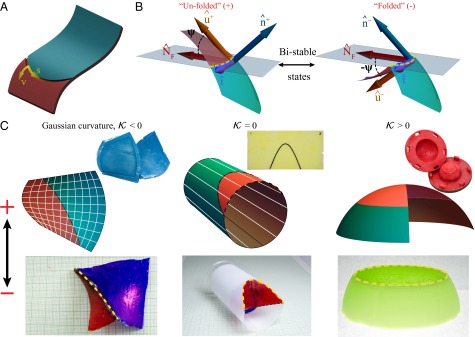
Fig. 1.

Folding of curved shells along a crease. (A) Creasing a shell involves thinning the shell locally along a curve that lies on the surface to form a “trench.” A local coordinate system on the crease is indicated. (B) Natural and folded states of a creased shell, denoted as the “+“ (unfolded) and ”−” (folded) conformations. Tangent and normal vectors to each surface “” are given by and , respectively. is the normal to the curve, whereas indicates the tangent to both the crease and the surface. The angle ψ between and is also indicated. (C) Schematics (for +) and creased experimental samples (for −) for all three prototypical geometries: helicoid (), cylinder (), and spherical shell (). (Insets) Three-dimensional printed molds with embossed ridge to realize creases on () geometries, and a scored sheet for the () case. Examples of curves with are marked on schematics in white lines, and creases are marked on experimental samples with dotted yellow curves.
