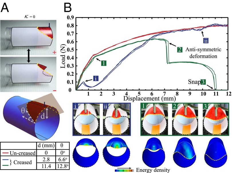
Fig. 3.
Folding of cylinders (). (A) Bistable states (+, −) of a cylinder with appropriate planar crease. Crease parameters d (distance of the osculating plane from the apex) and angle θ (from horizontal) are shown in the schematics, along with values for for the representative samples studied in this experiment. The radius of the cylinder is 25 mm. (B) Force–displacement curves for uncreased (red), crease with mm (blue) exhibiting monostable behavior. In contrast, a creased cylinder with mm (green) exhibits an antisymmetric behavior leading to a bistable snapped state. Snapshots from experiments and FEA simulations show different stages of deformation. A contact-slip profile is seen at higher displacements for these samples. See, additionally, Movie S2.

