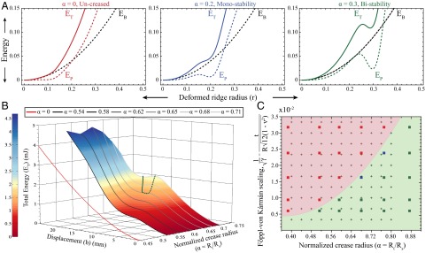
Fig. 5.

Stability of creased spherical shells (K > 0). (A) For an uncreased shell, the energy of an indented shell is composed of the bending energy (black dotted) and the Pogorelov ridge (colored dotted). For a creased shell takes a substantial dip localized at , but the total energy (colored solid) only has a local minimum if the crease is large enough. In these schematics the function is chosen to mimic the profile provided by experimental molds. (B) Numerically calculated energy landscape for a creased shell with for a variety of α. The Pogorelov solution is recovered for (red plot), whereas for small values of α the energy gain from the crease is insufficient to create a local minimum. However, above a critical α, local minima (solid green) and maxima (dashed green) bifurcate to generate a region of stability. (C) Phase diagram for snapping behavior of spherical shells over a wide range of geometrical parameters α and . Stability behavior in experiments is characterized as bistable ( , switches to folded state through a snapping mechanism), monostable (
 , prefers unfolded state), or temporarily stable (
 , closer to phase boundary: snap back on a timescale of seconds without external perturbations). Finite-element simulations (points solved denoted with +) provide regions of monostability (red shading) and bistability (green shading). Each experimental data point was analyzed for at least three shells of appropriate parameters.
