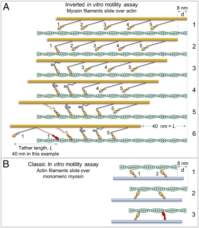
Fig. 4.
Comparison of attachment- and detachment-limited models. Actin (green) affixed to coverslip (not shown for clarity), myosin filament backbone (orange) with protruding S2 (black) connecting to orange head (only one head shown). Frame numbers at right. (A) Hypothetical myosin filament moving in the inverted motility assay according to attachment-limited model. Working heads adjacent to one another are not likely (low duty ratio) and are shown as such only to illustrate the general idea. Frames: 1, no heads are attached; 2, head 1 attaches/undergoes powerstroke (A/P) moving filament d = 8 nm; 3, head 2 A/P while head 1 still attached, but head 1 places minimal drag load on filament due to flexible S2, therefore d = 8 nm once again; 4, head 3 A/P, buckling S2 of head 1 further and head 2; 5, after head 4 A/P, the S2 region of head 1 now begins to place some drag load on the filament; 6, after head 5 A/P, the S2 region of head 1 (red) is now fully stretched into a drag position, placing maximal drag load onto the filament, further heads working will not move the filament until head 1 detaches (now the filament is in a detachment-limited situation). The S2 tether length, L, is arbitrarily set to 40 nm. (B) Monomeric myosin heads in the classic IVMA. S2 (not shown) is interacting with coverslip (blue). Frames: 1, no heads attached; 2, head 1 A/P giving d = 8 nm; 3, head 2 attaches but d << 8 nm due to load placed on actin by head 1, head 2 is strained (red) because it cannot undergo full powerstroke.

