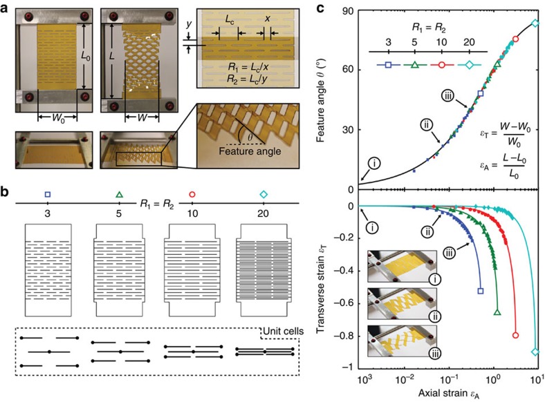
Figure 2. Kirigami cut geometry and geometric system response.
(a) Response of a Kapton kirigami structure to stretching in the axial direction (ɛA) is accompanied by a decrease in sample width (ɛT) and a change in feature angle (θ). Also shown are the geometric parameters that define the kirigami structure, namely the cut length (LC) and spacing between cuts in the transverse (x) and axial (y) directions, which can be expressed in terms of the dimensionless parameters, R1 and R2. (b) Schematics of four kirigami structures, where R1=R2=3, 5, 10 and 20, along with their corresponding units cells. (c) ɛT and θ versus ɛA for several kirigami structures where R1=R2=3, 5, 10 and 20 (b). Theoretical predictions per equations (1) and (2) are shown by solid lines, while the closed symbols represent experimental data from a 50 μm-thick Kapton sample of the appropriate geometry. While larger R1 and R2 enable increased axial strains and correspondingly larger transverse strains, the change in feature angle is independent of cut geometry.

