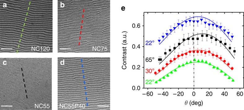
Figure 2. Determination of magnetization canting angles.
(a–d) Normal incidence 4.65 × 4.65 μm2 images of NC120, NC75, NC55 and NC55P40 films at remanence, showing the stripe domain pattern typical of systems having perpendicular magnetic anisotropy. Dotted lines indicate the profiles used to evaluate the magnetic contrast. Scale bars, 1 μm. (e) Measured (symbols) and calculated (continuous lines) contrasts of the four films (NC120, green up triangles; NC75, red circles; NC55, black squares; NC55P40, blue down triangles) at different angles θ. The fitted values of φ are indicated close to the corresponding curves; error bars were evaluated from s.d. of the intensity along the center of the stripes.

