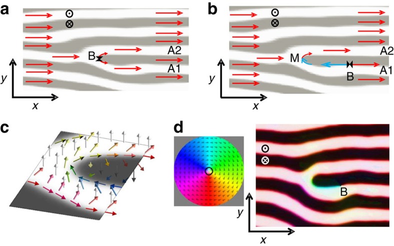
Figure 5. Magnetization configuration at a dislocation core during in-plane magnetization reversal.
(a) Sketch at remanence with positive Mx (red arrows) in all the stripe pattern, including the dislocation branches A1 and A2. Topological restrictions indicate that a singular Bloch point (B) must appear at the core where the two equally magnetized branches meet tail-to tail along the Bloch wall; x and y axis, and z sense are indicated. (b) Sketch with a Mx reversed domain (blue arrows) bounded by a Bloch point (B)—meron (M) pair. (c) Three-dimensional (3D) sketch of magnetization (coloured arrows) around a dislocation core with meron. (d) 3D micromagnetic simulation of NC layer at central plane showing a Bloch point (B)–meron pair; colour code used to depict the simulated magnetization direction is shown in the coloured wheel.

