Figure 3.

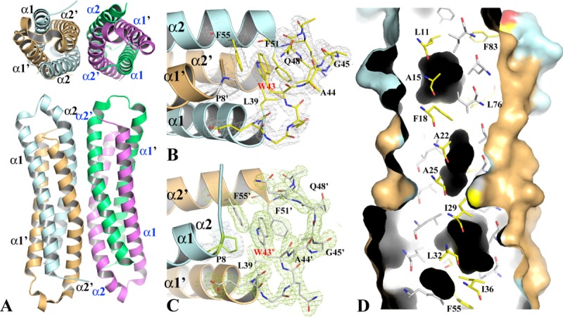
The structure of WT-EsxB-His6 BU dimer and tetramer. (A) The top and side views of the two WT-EsxB-His6 BU dimers in asymmetric unit. The possible tetramer assembly was deduced by PISA16 analysis. The dimer on the left side, formed by monomers A (in pale cyan) and B (in light orange) is used as a model for the detailed structural description provided in the text. (B) and (C) The structures of the inter-helix links of monomers A and B, respectively. The links from different dimers drawn in stick format show their different conformations. The link from monomer A contains a one-turn helix while link B contains two β-turns. The 2FoFc electron density maps of both link regions are contoured at 1σ. (D) Molecular surface representation and ribbon diagram of a portion of the BU dimer. The dimer is cross-sectioned from one side to show the packing of the core of the helical bundle as well as cavities (in black) resulted from the packing. Key residues contributing to the packing are drawn in stick format. Primes on secondary structures refer to those from monomer B. For clarity, only residues from monomer A are labeled. The corresponding residues from monomer B are related to them by a twofold symmetry.
