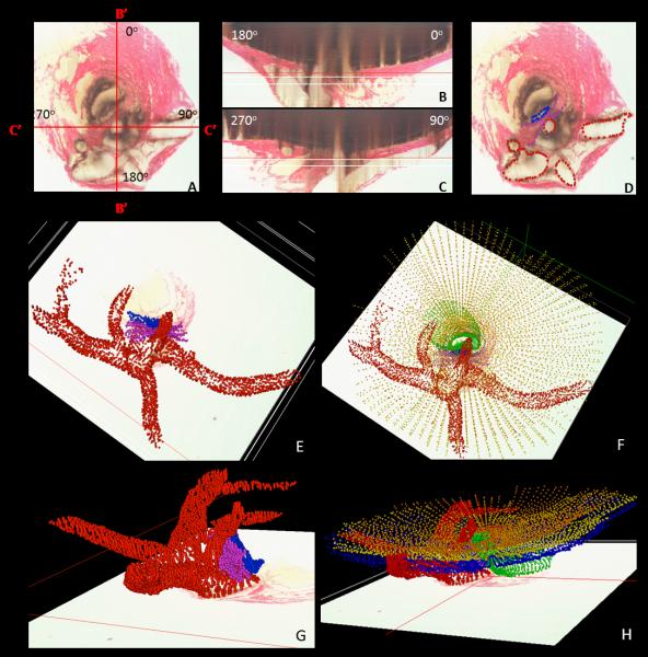
Figure 4. 3D Delineation of the ONH and Peripapillary Scleral Vasculature and Scleral Sling within Digital Transverse Section Images.
Vessel and scleral sling delineation were performed within every fourth digital transverse section image (A) while simultaneously viewing one linked window which displayed either embedded vertical (B) or embedded horizontal (C) digital sagittal sections through the point being delineated. The lines marked B’-B’ and C’-C’ in panel (A) mark the location of the embedded vertical and embedded horizontal digital sagittal section images depicted in panel (B) and (C), respectively. Note that these are vertical and horizontal sections through the 3D reconstruction, but because the tissues are not embedded in perfect clinical orientation, they are not “anatomic” vertical and horizontal sections through the ONH. In Figure 2, this same reconstruction has been turned so that an accurate clinical orientation has been achieved and “anatomic” vertical and horizontal sections are shown. The following landmark categories were individually marked and catalogued within each delineated transverse section image (D): Ophthalmic artery (OA - red); (2) Central retinal artery (CRA - red);(3) Long posterior ciliary arteries (LPCA - red); (4) Short posterior ciliary arteries (SPCA – reds – and branches of the LPCAs in rats); (5) Central retinal vein (CRV - blue); and (6) the vascular or neural boundary of the scleral sling (magenta). Three dimensional reconstructions of the landmark point clouds (panels E - H) were then 3D visualized together and separately (turning each landmark category on and off) so as to determine their principal macroscopic relationships.

