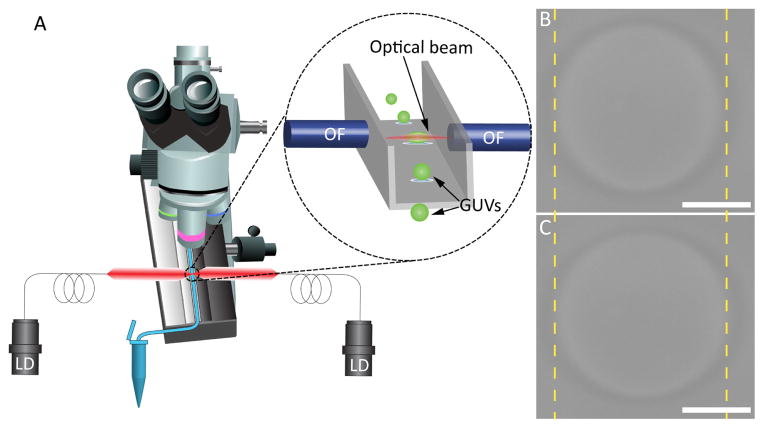
Fig. 1.
Schematic illustration of the DBOT apparatus and its trapping mechanism. (A) A schematic of a microscope integrated with a microfluidic channel and two fiber-coupled laser diodes. The inset is the magnified image of the trapping site, where the optical fibers are positioned towards a square glass capillary tube. Optical images of a trapped GUV (B) with 100 mW laser power and (C) with 500 mW laser power. The scale bars are 10 μ m.

