. 2015 Jun 23;4:e07090. doi: 10.7554/eLife.07090

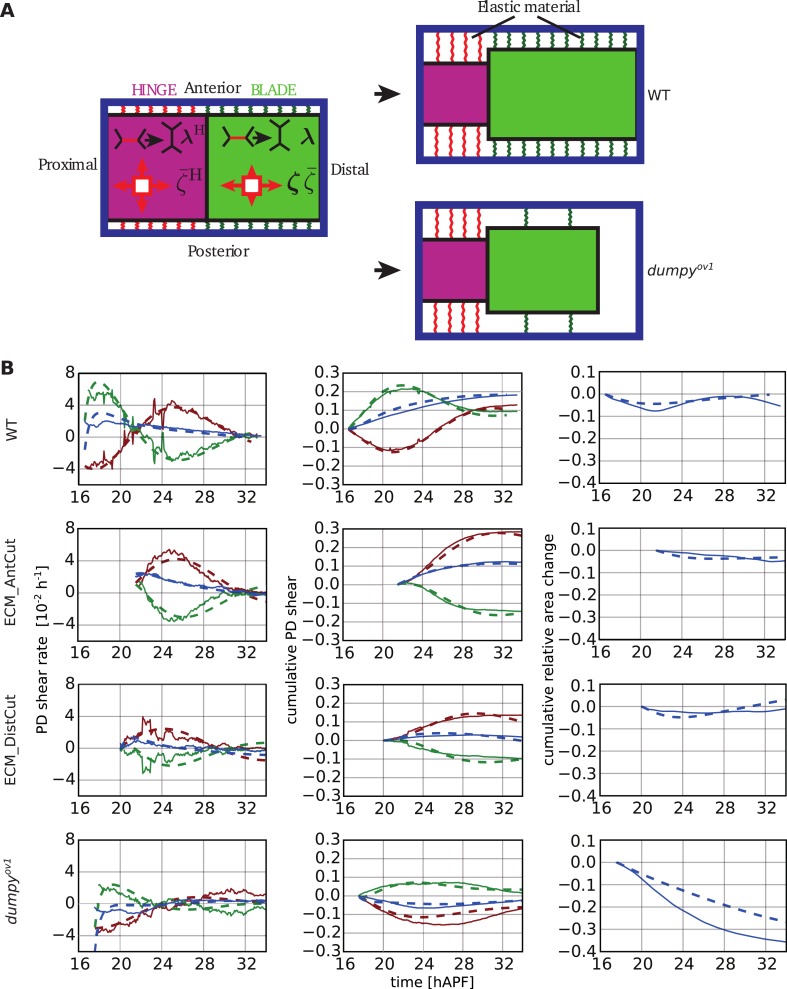
Figure 10. Continuum mechanical model of wing morphogenesis.

(A) Schematics of the wing model: the hinge and blade are represented by rectangles. Within each rectangle, the tissue is subjected to cell-autonomous anisotropic and isotropic stresses ζ and ζ¯, and to topological changes driven by cell polarity-dependent processes λ. The complex elastic material connecting the wing to the cuticle is represented by AP-oriented elastic links (green and red springs on the cartoon) and PD-oriented springs (see Figure 10—figure supplement 1). In WT wings, the blade distal end is fixed, while it is free to move in the dumpyov1 mutant. (B) (Left) Experimental (solid line) and theoretical (dashed line) time courses of tissue shear rate (blue curves), cell elongation change (green curves) and shear due to topological changes (red curves), in the blade and along the PD axis. (Middle) Experimental and theoretical time courses of cumulative tissue shear (blue curve), cell elongation (green curve) and cumulative shear due to topological changes (red curves), in the blade and along the PD axis. (Right) Experimental and theoretical cumulative relative blade area change. Model parameters were obtained by a fitting procedure to experimental data (Tables 1, 2). The continuum mechanical model recapitulates cell shape changes and tissue flow during wing morphogenesis.

DOI: http://dx.doi.org/10.7554/eLife.07090.033

Figure 10.

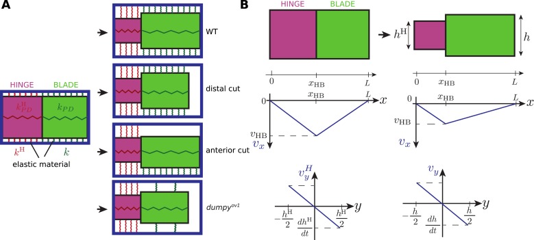
Figure 10—figure supplement 1. Schematics of the rectangle model.

Figure 10—figure supplement 1.

(A) The hinge and blade are represented by two rectangles connected to an external frame representing the cuticle (blue rectangle). AP-oriented elastic springs at the anterior and posterior sides, with elastic moduli kH and k, resist change of heights of the rectangle. In addition, two PD-oriented elastic springs constrain the length of the hinge and blade with elastic moduli kPD and kPDH. In WT wings, the blade is firmly attached distally to the cuticle. To represent the wing whose ECM is ablated distally, a free boundary is introduced on the distal side of the blade rectangle. Similary, anterior ablation of the ECM is represented by removing anterior springs, k = 0. To represent the dumpyov1 mutant, distal links are removed while anterior and posterior links are weakened. (B) Geometry of rectangle deformation. The position of the hinge-blade interface is labeled xBH, the total length of the wing L, the heights of the hinge and blade hH and h. Lower plots: representation of the velocity profiles in the x and y direction in the hinge and blade, in the rectangle model, for WT wings.
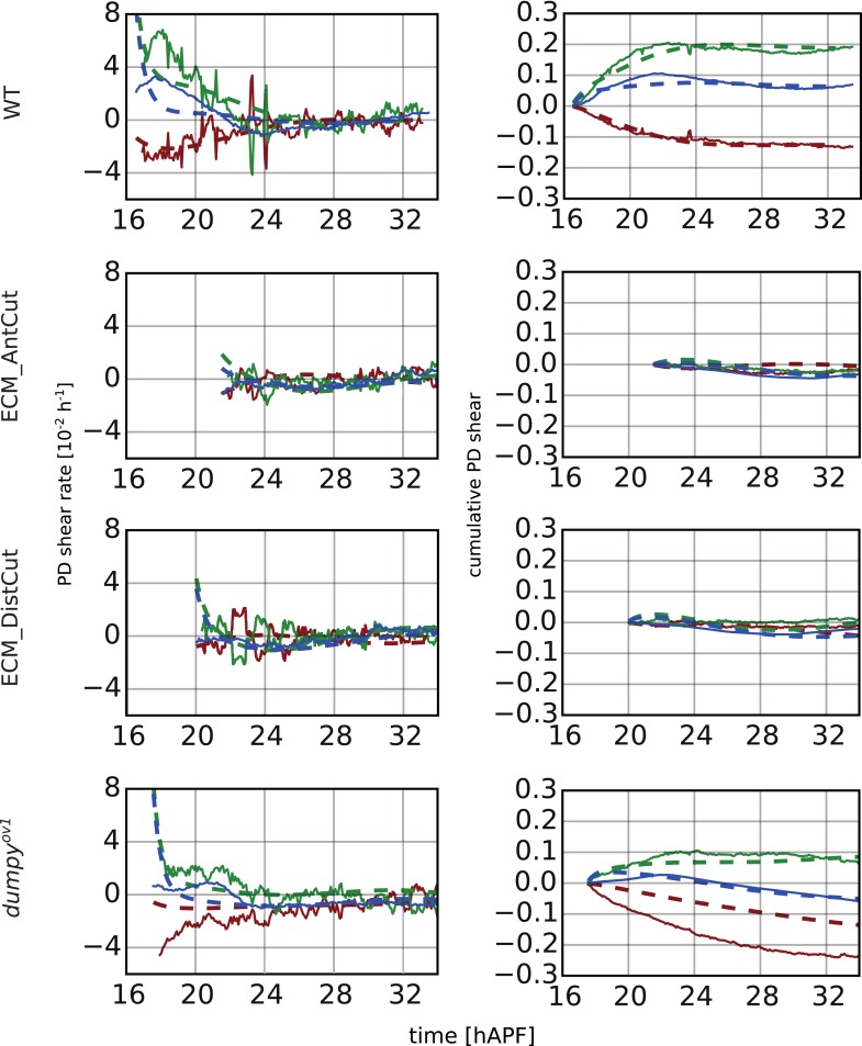
Figure 10—figure supplement 2. Continuum mechanical model in the hinge.

Figure 10—figure supplement 2.

(Left) Experimental and theoretical time courses of tissue shear rate (blue curves), cell elongation change (green curves) and shear due to topological changes (red curves), in the hinge and along the PD axis. (Right) Experimental and theoretical time courses of cumulative tissue shear (blue curve), cell elongation (green curve) and cumulative shear due to topological changes (red curves), in the hinge and along the PD axis. Model parameters were obtained by a fitting procedure to experimental data (Tables 1, 2).