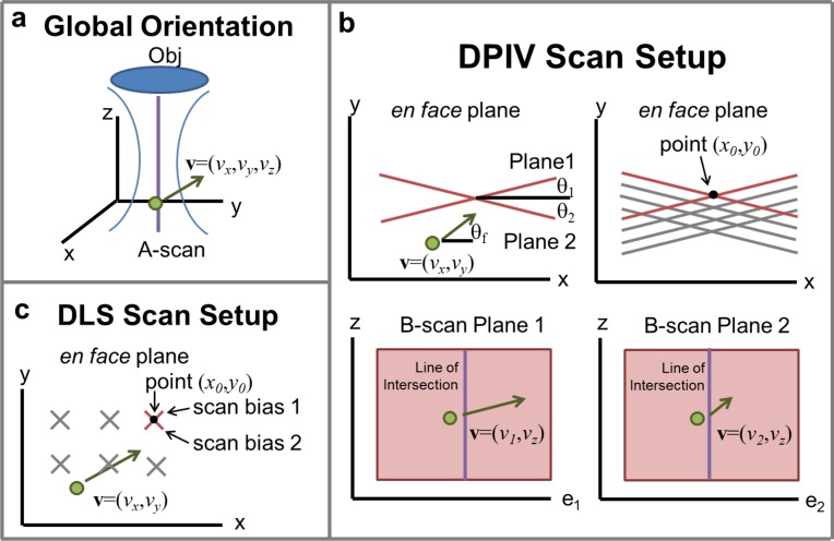
Fig. 2.
Scan setup for DPIV and DLS-OCT. (a) Three-dimensional coordinate system, with optical axis defined along z, and en-face plane defined as xy-plane. A particle with velocity v = (vx, vy, vz) can be decomposed into three components based on this Cartesian system. (b) DPIV scan setup, showing (top left) two non-orthogonal plane measurements. The angle of each scan plane, θ1 and θ2, as well as the angle of flow in the en face plane θf, are all defined with respect to the global x-axis. The velocity as measured by DPIV in each plane is the vector component of the velocity v on the unit vector tangent to the plane, either e1 or e2 (bottom left / right). The vector projections of velocity in these two planes are denoted as v1 and v2. From v1 and v2, vx and vy can be calculated along the line of intersection at these planes. Acquiring multiple scan plans (top right) allows for calculation of v at multiple points (x0, y0), to reconstruct an entire 3D volume. (c) DLS-OCT scan protocol showing series of scan bias acquisitions. Each line measurement along z-axis at location (x0, y0) in the en face plane consists of a set of scans along axes oriented around ±45°. Much like the DPIV measurements, the directional DLS-OCT protocol yields two velocity measurements v1 and v2. vx and vy can then be recovered along a single axial line using Eqs. (3) and (4). These scans are then repeated at various (x0, y0) points.

