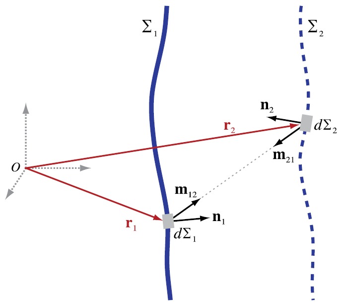
FIG. 13.

(Color online) As used for field projection calculations, two surfaces and are depicted schematically relative to a coordinate system with origin O. Each surface corresponds to the locus of points represented by position vectors or , respectively. represents a boundary surface with an acoustic source that radiates waves into the half-space region that includes . This surface is further described by the outward facing unit normal and differential area elements . is described by analogous notation and represents a non-physical surface at which field measurements are made.
