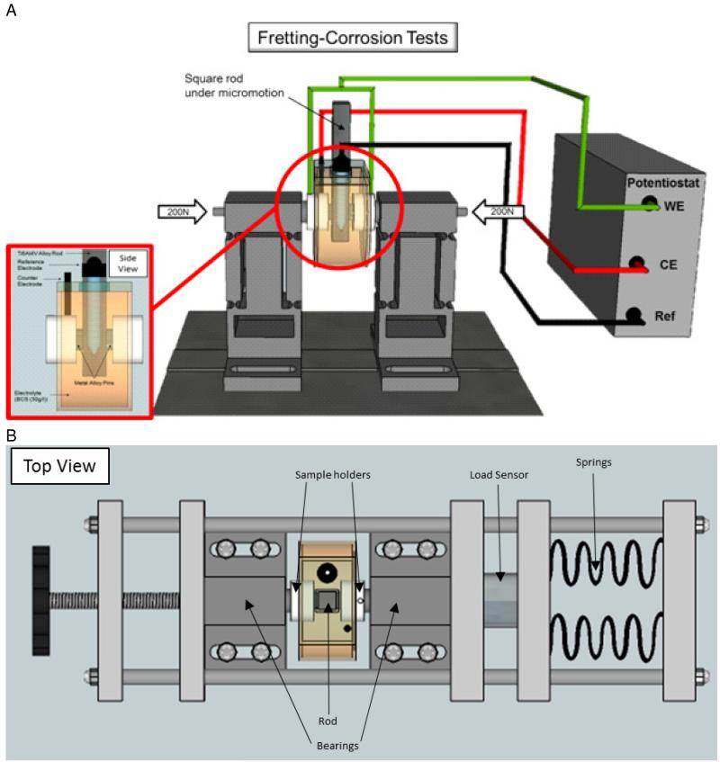
Figure 1.
(a) Fretting corrosion test chamber with a square rod undergoing micro motion against two, axially loaded, metallic pins. Electrode configuration consists of metallic pins coupled with the rod as the working electrode (WE), a graphite rod as the counter electrode (CE), and a saturated calomel electrode as the reference electrode. (b) Top view of the complete setup, including the load frame, which applies load axially onto the bearings. The bearings transmit the load through the sample holders, to the pins, onto the rod. The applied load is measured by a load sensor.

