
Fig. 4.
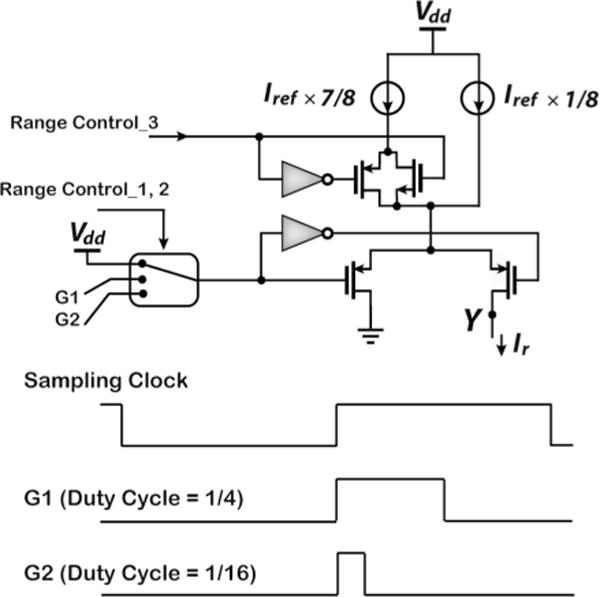
Illustration of range selection mechanisms. (Top) Circuitry for scaling Iref. (Bottom) G1 and G2 signals drawn with respect to the sampling clock for modulating the duty cycle of Iref in method (2). Sampling occurs at the negative edges.
Official websites use .gov
A
.gov website belongs to an official
government organization in the United States.
Secure .gov websites use HTTPS
A lock (
) or https:// means you've safely
connected to the .gov website. Share sensitive
information only on official, secure websites.
Illustration of range selection mechanisms. (Top) Circuitry for scaling Iref. (Bottom) G1 and G2 signals drawn with respect to the sampling clock for modulating the duty cycle of Iref in method (2). Sampling occurs at the negative edges.