
Fig. 7.
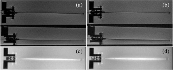
RTFSE images of the biopsy needle with and without optical fibers and FBGs show the same degree of needle artifact. (a) Unmodified needle, coronal and sagittal view. (b) Modified needle, coronal and sagittal view. Maximum intensity projections (MIP) through a 3-D volume of acquired images show the cumulative bright artifact caused by the needle. The amount of artifact between the two needles is comparable. (c) MIP of the unmodified needle. (d) MIP of the modified needle.