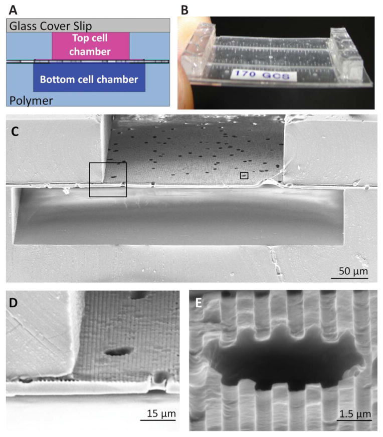
Fig. 4.
The topographically-patterned membrane assembled into a microfluidic device. The overall cross-sectional architecture of a device (A) was formed by a glass coverslip and two PDMS cell culture chambers separated by the patterned porous membrane. The thin nature of the device (B) allowed high-resolution imaging of cell populations on either side of the porous membrane. An SEM cross section (C) of the device shows the porous nature of the membrane separating the top and bottom chambers, while insets (D) and (E) show close-ups of well-defined groove topography coexisting with the porous architecture.

