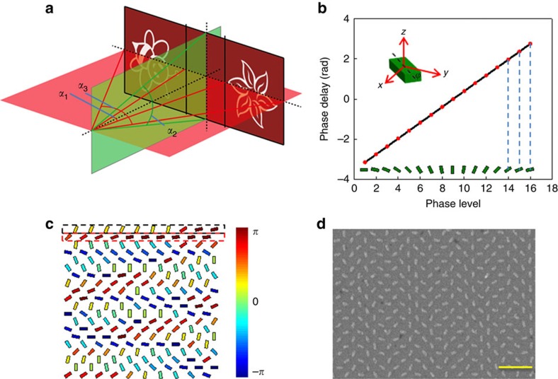
Figure 3. The designed metasurface hologram and the fabricated sample.
(a) Geometric parameters of the projected images that correspond to the merged hologram. The full off-axis angle α1, target image angles α2 and α3 are designed to be 20.7°, 22° and 64.7°, respectively. (b) Phase delay for the different phase levels. Sixteen phase levels (−π to π with the interval of π/8) are used in the design. On each red point, the orientation of the corresponding nanorod is given. The orientation of each nanorod is defined as the angle between the long axis of the nanorod and the y axis. (c) Schematic of the nanorod distribution for the merged metasurface hologram. The phase levels are denoted by the different colours of the nanorods. The nanorods in the rows with odd number and even number contribute to the reconstruction of ‘bee' and ‘flower', respectively. (d) Scanning electron microscopy image of part of the fabricated metasurface. Each nanorod represents a phase pixel defined in the hologram. Scale bar, 1 μm. The equivalent pixel size is 300 × 300 nm2.

