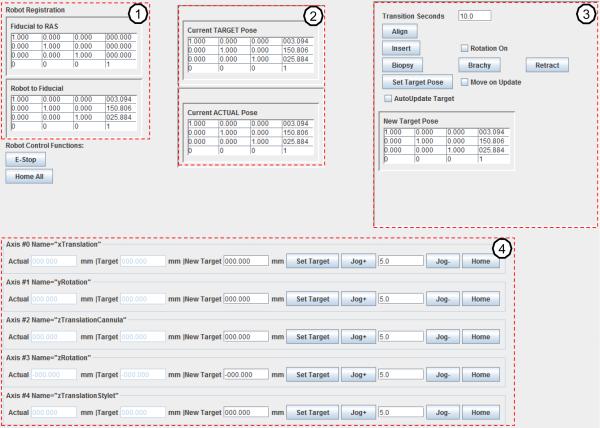
Fig. 8.
The GUI of the robot control software running on the control computer in control room. The upper left column (1) is robot registration and calibration, the upper middle column (2) displays the current target point transformation and current actual robot 6-DOF pose. The upper right column (3) contains the desired target transformation and buttons to control biopsy or brachytherapy procedures. The bottom row (4) is the joint space panel.

