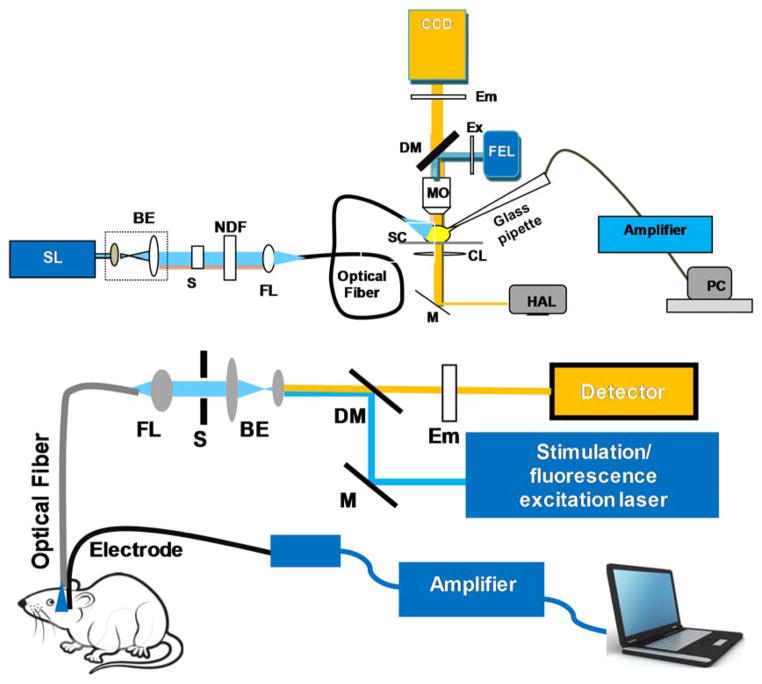
Figure 3. Typical experimental set ups for optogenetic stimulation and characterization.
Top: In-vitro optogenetic stimulation set up integrated with patch clamp recording and optical imaging ability. SL: Stimulation Laser; BE: Beam Expander; S: Shutter; NDF: Neutral Density Filter; FL: Focusing Lens for coupling to optical fiber; FEL: Fluorescence Excitation Lamp; Ex: Excitation Filter; DM: Dichroic Mirror; Em: Emission Filter; MO: Microscope Objective; SC: sample Chamber; CL: Condenser Lens; M: Mirror; HAL: Halogen Lamp. Bottom: Set-up for in-vivo fiber-optic optogenetic stimulation, electrophysiological recording and optical detection. M: Mirror; DM: Dichroic Mirror; Em: Emission Filter.

