Figure 2.

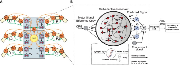
(A) Neural mechanisms implemented on the bio-inspired hexapod robot AMOSII. The yellow circle (CPG) represents the neural locomotion control mechanism (see Supplementary Figure 1). The gray circles (RF1, 2, 3, …, 6) represent the reservoir-based adaptive forward models. The green circles (SE1, 2, 3, …, 6) represent searching and elevation control modules. The orange circles represent leg joints where TRi, CRi, FRi are TC-, CTr- and FTi-joints of the right front leg (i = 1), right middle leg (i = 2), right hind leg (i = 3) and TLi, CLi, FLi are left front leg (i = 1), left middle leg (i = 2), left hind leg (i = 3), respectively. BJ is a backbone joint. The orange arrow lines indicate the motor signals which are converted to joint angles for controlling motor positions. The black arrow lines indicate error signals. The green arrow lines indicate signals for adapting joint movements to deal with different circumstances. (B) An example of the reservoir-based adaptive forward model. The dashed frame shows a zoomed in view of a single reservoir neuron. In this setup, the input to each of the reservoir network comes from the CTr-joint of the respective leg. The reservoir learns to produce the expected foot contact signal for three different walking gaits (z1, z2, z3). The signals of the output neurons are combined and compared to the actual foot contact sensory signal. The error from the comparison is transmitted to an integrator unit. The unit accumulates the error over time. The accumulated error is finally used to adapt joint movements through searching and elevation control.
