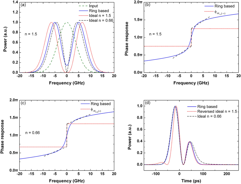
Figure 3. Differentiator based on the over-coupled microring resonator.
(a) Power spectra of the input Gaussian pulse, output differentiated signal, and ideal differentiated signals with the differentiation orders of n = 1.5 and n = 0.66. (b) Phase response of the microring-based differentiator and  . (c) Phase response of the microring-based differentiator and
  . (d) Outputs of the microring-based differentiator (blue solid line), time-reversed ideal 1.5-order differentiator (red dotted line), and ideal 0.66-order differentiator (black dash-dotted line). The time delays are neglected.

