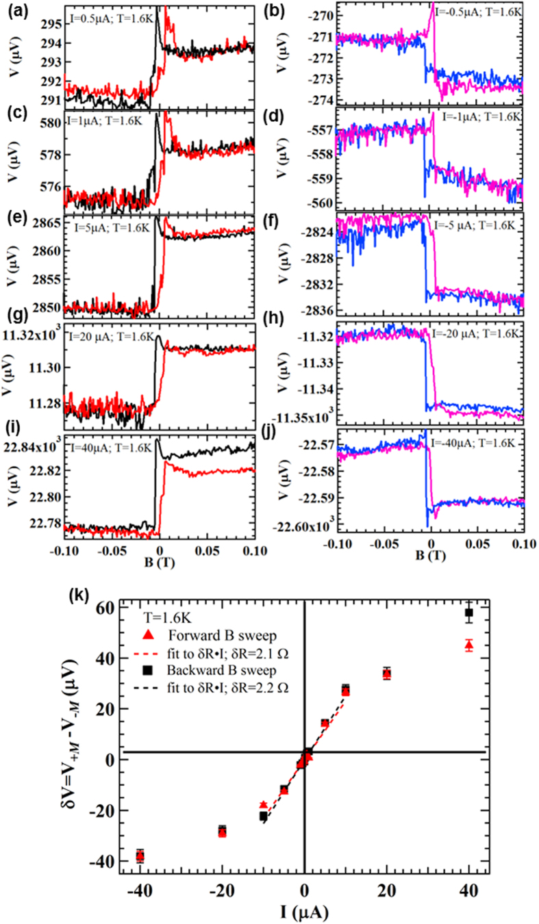
Figure 3. Current dependence of the measured spin signal.
(a–j) Voltage measured by the Py spin detector on device A as a function of in-plane magnetic field at different bias currents of 0.5 μA (a), −0.5 μA (b), 1 μA (c), −1 μA (d), 5 μA (e), −5 μA (f), 20 μA (g), −20 μA (h), 40 μA (i), −40 μA (j). (k) Amplitude of the voltage change δV = V+M–V−M as a function of the applied bias current. Here, V+M and V−M are the average voltages measured between (0.04 T, 0.06 T) and (−0.06 T, −0.04 T) respectively. The red/black symbols represent the result extracted from the red/black curves (forward/backward magnetic field sweep). Dashed lines are linear fits to the data between −10 μA and 10 μA (in the liner response regime). All the measurements are performed at T = 1.6 K.

