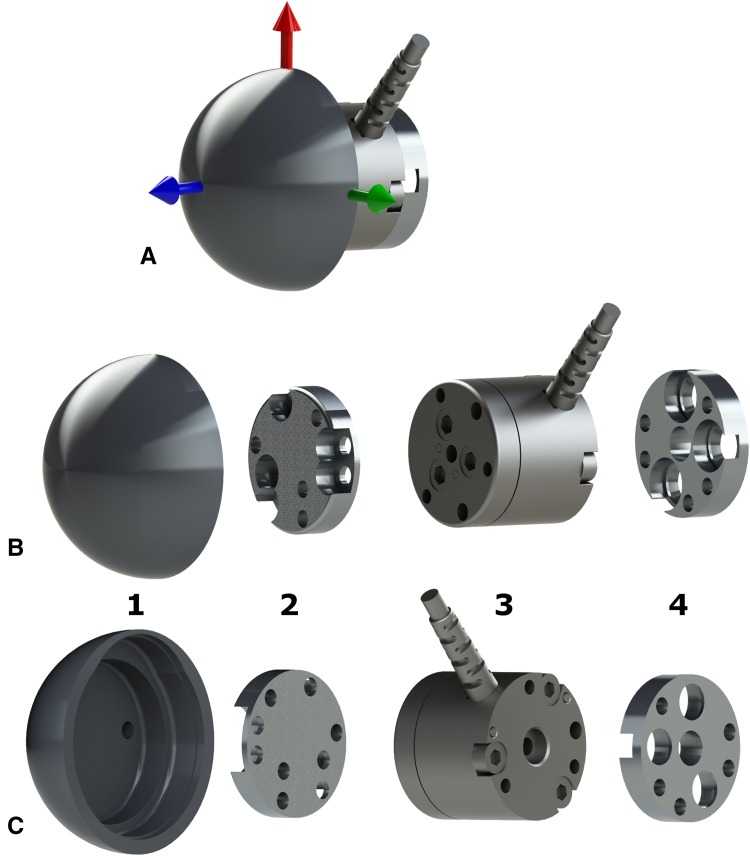
Fig. 2A–C.
A computer rendering of the custom modular glenoid implant shows (A) an isometric view of the assembled glenosphere components with coordinate frame indicating the load measurement directions; (B) an isometric exploded view of the four glenoid components separated: a custom 38-mm diameter hemispheric glenosphere component with hollowed-out back (1), a 5-mm (also 0 and 10 mm) glenosphere lateralization spacer which nests in the hollow of 1 (2), a six-axis load sensor designed to nest in the hollow of 1 and in the reamed glenoid fossa (3), and a glenosphere baseplate for fixation of the glenoid implant to the scapula (4); and (C) the reverse angle of the isometric exploded view.

