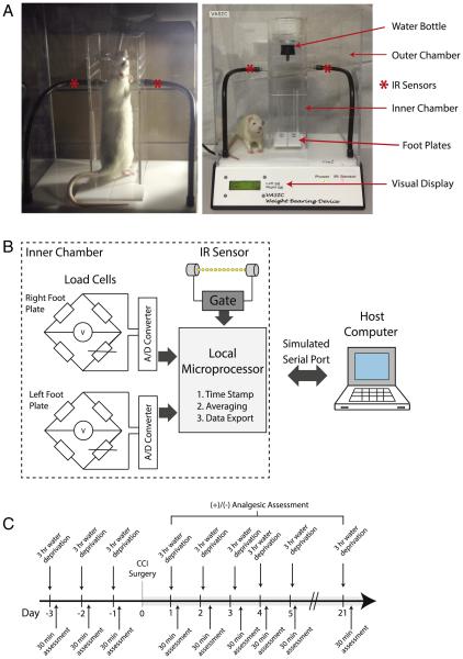
Fig. 1.
Voluntarily Accessed Static Incapacitance Chamber (VASIC). A. Photographs of the VASIC device showing the outer and inner plexiglass chambers, water bottle, IR sensors, and footplates. Photo on the left shows a typical self-positioning of an animal on the footplates inside the inner cage. As the animal accesses the water mounted on top of the inner chamber, the IR beam is broken and recording is initiated. The load cells are positioned underneath the footplates which feed the real-time weight information every 100 ms. B. A block diagram of the major components of the device. The load cells placed under the footplates transduce the weight into analog signals that are converted by the analog-to-digital (A/D) converter and subsequently processed by a local microprocessor for time stamp, signal averaging, and data export via a Windows simulated serial port to the host computer. The IR sensor gates the transfer of data. C. A timeline of a typical experiment indicating the pre-surgery water restriction conditioning for 3 days and a daily assessment of the weight distribution with VASIC.

