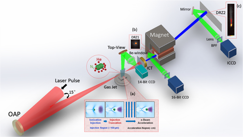
Figure 1. Schematic diagram of the experimental setup.
Up to 118 TW 30 fs laser pulses are focused down to 28 μm spot size with an OAP (f = 2 m) onto 4 mm or 1 cm supersonic gas jet of He and N2 gas mixture. The self-truncated ionization injection (STII) mechanism is illustrated in inset (a). Inset (b) shows a fixed fluorescent DRZ screen for monitoring the electron beam pointing and divergence angles before entering the magnet. Inset (c) is an electron beam energy spectrum. Top-view imaging system monitors the laser-plasma. ICT stands for integrating-current transformer used to measure the beam charge. The laser-produced plasma density was probed (not shown) in earlier experiments by the authors via interferometry using a 100 fs probe beam and by FRS diagnostic.

