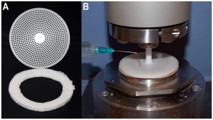
Figure 3.
Image of testing apparatus and PU rings. A) View of the bottom of the Delrin 60mm parrallel plate used in these experiments (top). Through holes were incorporated into the plate to reduce inertia and provide a means of sample loading. PU discs were cut into rings (bottom) for testing. B) Image of test set up with the PU ring compressed between the Delrin upper plate and sandpaper which has been adhered to the bottom plate. Sample loading can be accomplished through a needle and syringe.

