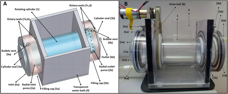
Figure 2.

Schematics of the second flow-through rolling tank designed (A) and a picture showing the mounted motor and rotating belt (B). The system described here is 30 cm long and the diameter of the inner tube is 9 cm. This design consists of a single cylinder (1) with 20 peripheral holes (2a–b) at each side through which water flows into and out of the cylinder. The cylinder is end-sealed with removable caps (3a–b). A transparent rectangular container mounts the cylinder (4). Two cylindrical caps (5a–b) encapsulate the inlet and outlet holes and act as reservoirs for entering and exiting water (6a–b) into and out of the cylinder. Both caps and the rectangular mount are stationary while the cylinder is mounted with rotary seals (7a–d) and may rotate by drive-belt (8). Bubble venting valves (9a–b) are mounted on both fixed caps. Detailed images of the individual parts and their dimensions are given in Fig. S2 and Table S2, respectively.
