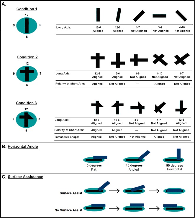
Fig 3. Illustrations of dependent variables for alignment of the sticks.
(A) Alignment of the long and asymmetrical portions of the stick. Shown in plan view, with clock face numbers used to categorize alignment of the long axis of the stick relative to the long axis of the cut-out (defined as 12–6). (B) Angle of contact, shown in side view. (C) Surface assistance, showing temporal succession of a successful attempt where the stick placement was guided by the cut-out. Shown in side view.

