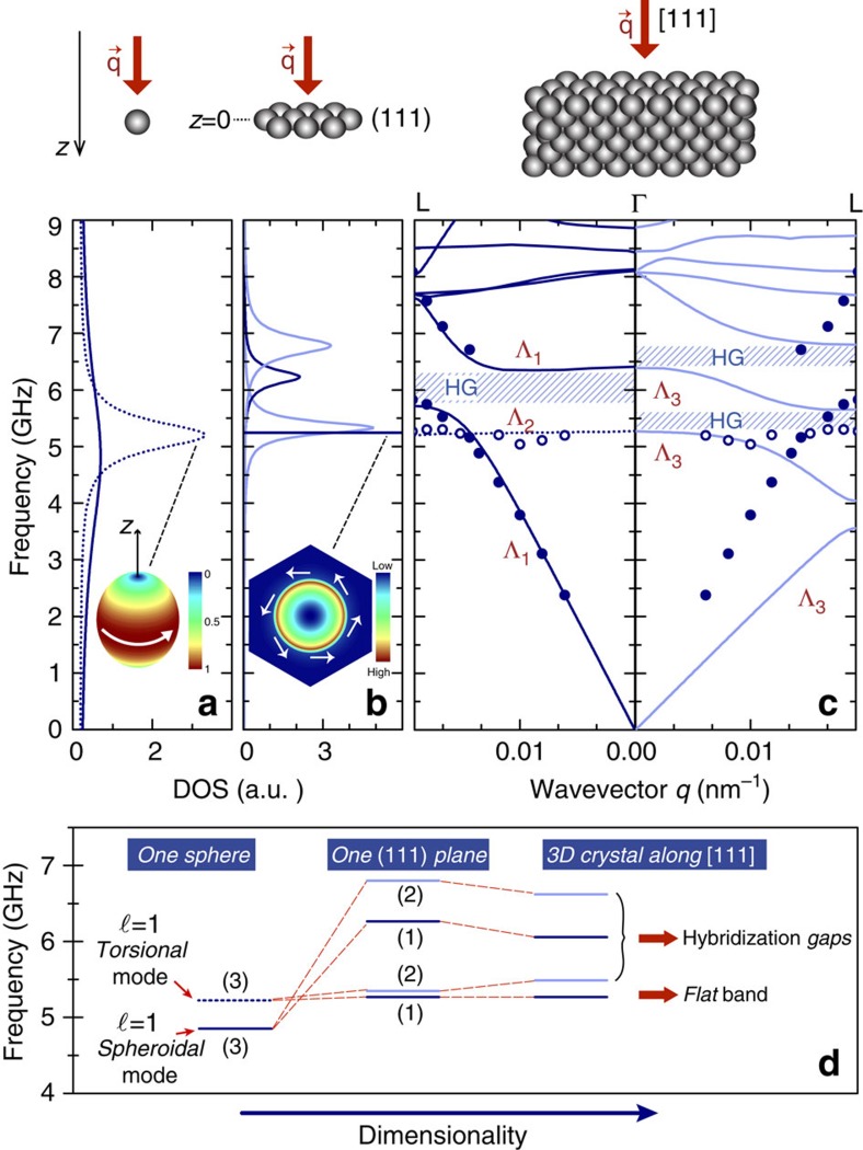
Figure 5. Physical origin of the dispersion characteristics and their evolutive formation with dimensionality.
Calculated DOS for (a) one SiO2 particle in PS (solid/broken lines spheroidal/torsional l=1 modes) and (b) for one (111) plane of particles of the DP600 film at slightly off-normal incidence (dark/light blue lines: non-degenerate/double degenerate modes). The mode corresponding to the very sharp peak in DOS plot of (111) plane, is associated to the flat band of the crystal (see c). Its field intensity representation within the unit cell passing at the centre of the sphere (z=0), at f=5.24 GHz, is shown in the inset. White arrows represent the quasi-pure rotational character of the field everywhere in the unit cell. (c) The band structure of the corresponding crystal along [111], with non-degenerate (left) and double degenerate (right) calculated bands together with the experimental points (symbols). The notation used is that of Fig. 3. (d) Schematic representation of the evolution of these modes when passing from a single sphere to the whole crystal. Parenthesized numbers denote the number of states per level. In the case of three-dimensional (3D) crystal, the levels indicating the hybridized modes correspond to HG centres.

