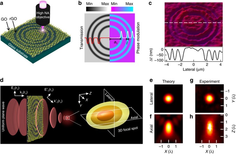
Figure 1. The design of the GO lens.
(a) Conceptual design and laser fabrication of the GO ultrathin lens. (b) Amplitude and phase modulations provided by the transmission and refractive index difference, respectively, between the GO and rGO zones. (c) Topographic profile of the GO lens measured with an optical profiler. (d) Left: Schematic of the wavefront manipulation by the GO lens converting the incident plane wave into a spherical wavefront. Right: Intensity distributions of the 3D focal spot predicted by the analytical model for a GO lens (a1=1.8 μm, N=3). (e,f) Theoretical focal intensity distributions in the lateral and axial directions. (g,h) Experimental focal intensity distributions along the lateral and axial directions.

