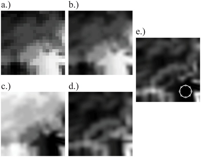
Fig 2. Steps to determine the in-focus area for the first (closest to the camera) image in the stack.
a) The original 20x20 pixel depth map was (b) up-sampled to 1080 pixels and smoothed with a Gaussian, so that (c) the distance in depth of each pixel from the first image’s focal depth could be computed. d) The local standard deviation of the depth image, computed over a 165x165 pixel region, was used to identify areas of uniform depth. e) The product of c and d: the white circle is centered on the location where this product has the lowest value (closest depth and lowest variance), to indicate the position of the in-focus patch at this depth.

