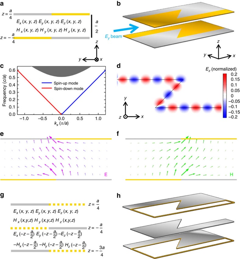
Figure 3. The spin-filtered edge mode between two parallel plate waveguides.
(a) Cross-sectional view of an edge between two parallel plate waveguides, each of which consists of a PEC plate and a PMC plate. (b) Oblique view of a zigzag edge where Ey-polarized EM wave is incident from the left. (c) Dispersion of the straight edge shown in a. The grey area represents the projected bulk modes in a single PEC–PMC parallel plate waveguide. Below its cutoff frequency of 0.5 (c/a), there exists only one spin-up forward edge mode (blue line) and one spin-down backward edge mode (red line). (d) Ez field pattern of the zigzag edge shown in b normalized by the incident field amplitude. The EM wave travels around two 135° corners without being reflected as the edge is spin-filtered. (e,f) Eigen electric field (magenta arrows) and magnetic field (green arrows) of the spin-up forward edge mode. To circumvent the complexity of using a PMC, we propose the periodic PEC configuration shown in g. The yellow dashed lines on z=−3a/4 and z=a/4 represent periodic boundaries. The periodic system in g has a field solution that corresponds to the solution of the system in a. Suppose the field solution of a consists of Ex(x, y, z), Ey(x, y, z), Ez(x, y, z), Hx(x, y, z), Hy(x, y, z) and Hz(x, y, z), which are non-zero in the domain z∈[−a/4, a/4]. The corresponding field solution of the periodic system is as illustrated in g. The spin-polarized robust transport in d can thus be realized for a broad range of frequencies by the periodic PEC plates shown in h.

