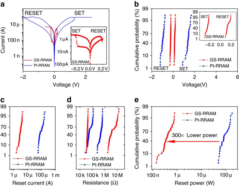
Figure 2. The device characteristics of GS-RRAM compared with Pt-RRAM and other emerging memory devices.
(a) Typical d.c. I–V switching characteristics of GS-RRAM and Pt-RRAM. For Pt-RRAM, SET process is observed when positive voltage is applied to TiN. For GS-RRAM, SET process is observed when positive voltage is applied to graphene. The SET compliances for GS-RRAM and Pt-RRAM are 5 and 80 μA, respectively, for optimum conditions. A magnified plot of GS-RRAM is shown as inset. (b) The SET and RESET voltage distribution of GS-RRAM and Pt-RRAM after 50 cycles of switching. The SET/RESET voltages of GS-RRAM are noticeably lower (inset). (c) Reset current distribution of GS-RRAM and Pt-RRAM after 50 cycles. GS-RRAM exhibit much lower reset current compared with Pt-RRAM. (d) Resistance distribution after 50 cycles for GS-RRAM and Pt-RRAM at 0.1 V. Larger memory windows are observed for GS-RRAM compared with Pt-RRAM. (e) Reset power distribution of GS-RRAM and Pt-RRAM. The power consumption of GS-RRAM is 300 times lower than that of Pt-RRAM. This is from the combined effect of lower programming voltages and currents.

