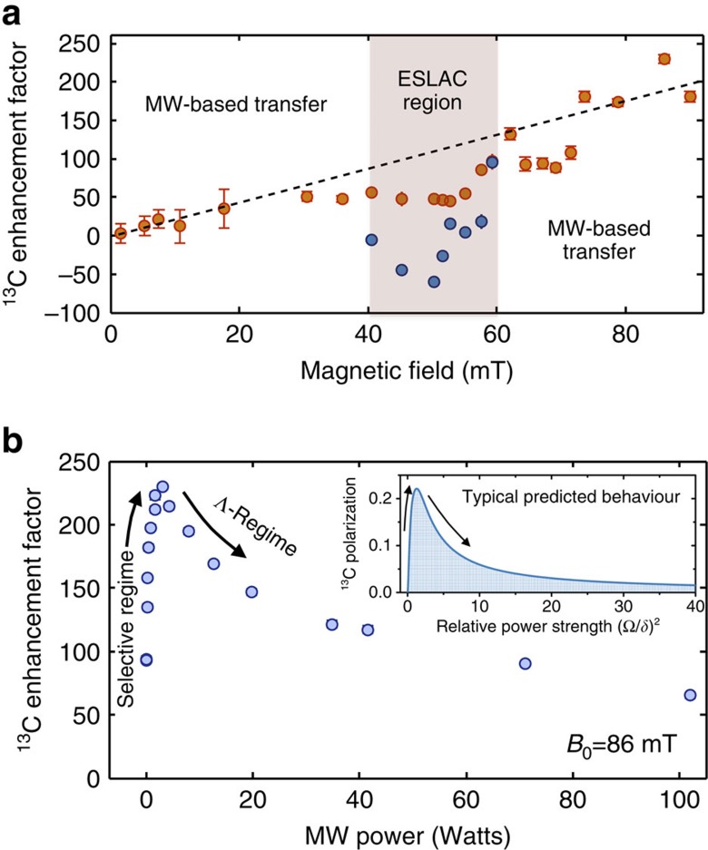
Figure 4. Ensemble 13C magnetization for different magnetic field strengths and MW powers.
The experimental points of these panels correspond to the maximum signal of the central peak in the aligned orientation. (a) 13C polarization as a function of the magnetic field strength B0 (normalized to its thermal 4.7-T counterpart and measured up to our maximum operating field, corresponding to ≈100 mT). The dashed line is a guide to the eye. Within the shaded excited-state level anticrossing (ESLAC) region polarization transfer was observed, deriving from the combined action between a level anticrossing mechanism12,13,14 and the here proposed MW-induced transfer scheme. These two nuclear polarization mechanism proceeded with opposing signs. Within this region, the blue dots show the resulting signal from the combined action of the ESLAC- and MW-induced transfer, while the orange dots show the MW-induced enhancement factor after a phenomenological subtraction of the 13C polarization transferred solely by the ESLAC scheme. (b) 13C hyperpolarization as a function of the MW power at a fixed field of ≈86 mT. The inset shows the typical predicted behaviour by the model, where the 13C polarization grows with MW power within the selective regime, but decreases as the Λ-regime is reached. As a qualitative comparison, the inset's numerical simulations consider a single NV centre coupled to a single 13C with an hyperfine interaction Azz=5Azx. In this case Δ=80δ, the laser-pumping rate=1.5/δ, the total polarization time=120/δ and the MW frequency is on resonance with the  transition. Qualitatively similar behaviours are obtained for different parameters. In both panels, the error bars represent the propagated relative error of the spin signal on the calculated enhancement factors.

