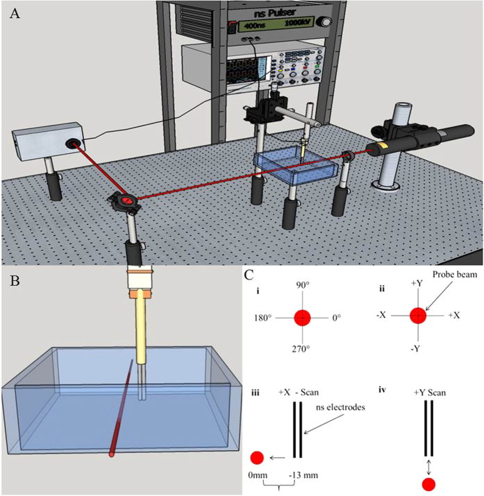
Figure 10.
(A) Schematic of PBDT setup. The probe beam passes through our exposure tank containing approximately 350 ml of physiological buffer solution and is directed into our custom quadrature diode detector. The nsEP electrode is positioned parallel to and at a fixed distance from the probe beam. The electrodes can be moved in either the X-plane or in the Y-plane. (B) Close up view of nsEP electrode in relation to the probe beam. The nsEP electrode is mounted on two motorized stages and can move up to 25 mm in the X-plane and up to 12 mm in the Y-plane. (C) Shows the relative orientation of the nsEP electrodes to the probe beam, i) polar coordinates used, ii) probe beam coordinates, iii) scan in the X-plane, iv) scan in the Y-plane. Drawings in Figures A–C were drawn by CCR.

