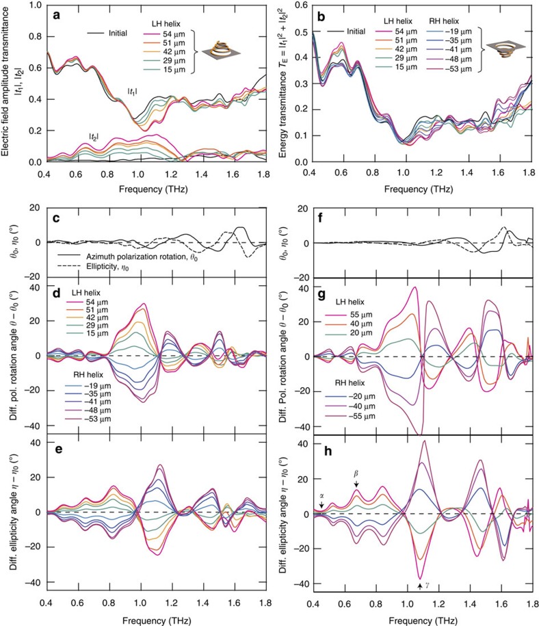
Figure 3. Experimental results of the proposed spiral metamaterial for different deformation conditions.
(a) Electric field amplitude transmittance. The black lines correspond to the condition of no applied pressure, wherein finite initial inclination exists. (b) Energy transmittance. (c) Azimuth polarization rotation θ0 and ellipticity η0 angles for the condition of no applied pressure. (d) Differential azimuth polarization rotation angles θ−θ0. (e) Differential ellipticity angles η−η0. The colour legend is as in d. (f) Calculated azimuth polarization rotation θ0 and ellipticity η0 angles for the condition of no applied pressure. Modelling details are provided in the Method section. (g) Calculated azimuth polarization rotation angle θ−θ0 spectrum for six deformation conditions. (h) Calculated differential ellipticity angle η−η0 spectrum for six deformation conditions, with the same colour legend as in g. Diff., differential; Pol., polarization.

