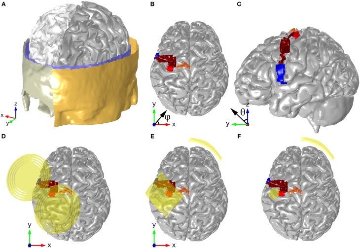
Figure 1.
Head model geometry, depicting the surfaces of the scalp, skull, CSF, GM, and WM (A). The position of motor and pre-motor areas are shown in panels (B,C): HK (red), SMA (orange), PMd (brown), and PMv (blue). The positions and orientations of the TMS coil, the electrodes in the montage with two 35 cm2 electrodes and the ones in the montage with the π cm2 anode are shown in panels (D–F), respectively. The angles shown in panels (B,C) represent the azimuthal angle (φ) and the polar angle (θ), respectively.

