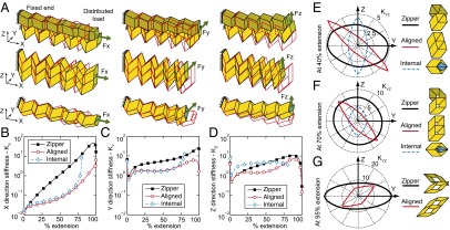
Fig. 4.

Zipper, aligned, and internally coupled tubes used as cantilevers. (A) Initial (red line) and deformed geometry of the structures at 70% extension when the left end is fixed and a uniform load is applied on the right end. The deformed shapes are scaled so the maximum displacement for each case is equal to the panel height () and do not necessarily represent stiffness. (B–D) The stiffness (force/length) of the cantilevers in the three Cartesian directions. The internally coupled tube cannot extend beyond 80% extension of the external tube. (E–G) The stiffness for loads in the plane represented as a radial plot at extensions of 40%, 70%, and 95%, respectively. Stiffness is shown as distance from the origin.
